If the Hiemer is out of commission or you don't feel like using it please see the steps below for proper use of the wiggler.
To find edges
- Insert disc end tool into collet, and hold collet in 3/8" tts holder.
- Align the tool along the z axis as straight as possible, turn on the spindle to 1000 rpm
- Jog the probe end near the axis that you wish to touch off, slowly step the probe disc tip touching the axis you are finding
- Jog until the disc is spinning perfectly concentric with the rotation axis. If probe spins wildly you stepped to far, back off one step, zero, realign to spinning axis and try again, you should only be a few thousands off.
- Repeat for other axis (if you did x, do y, or reverse)
- Now you need to compensate for radius of the disc .05
For more info and video demonstration please watch the video below
https://www.youtube.com/watch?v=RhtBdar4iVg
- Put a measured tool in to the spindle, making sure path pilot know that tool is being held and the tool offset length is correct
- Place z gauge block on your zero plane (top of stock: z zero is top surface/ Bottom of stock: bottom of vice/bed/fixture plate/top of parallels/etc)

- Jog tool down until dial reads zero on both major and minor dial
- On the offsets page enter gauge block height (50mm or 1.9685" if using provided gauge block) in field above "TOUCH Z"
- Click "TOUGH Z"
- Notice offset for Z height has adjusted
If a Heimer is not available to square a vice you must use a dial indicator.
- The first step is to always start with a clean vice and work surface, so remove any all chip, shmoo, debris from between any mating surfaces (clean the bed & the bottom of the vice)
- Carefully and with control place the vice and fixture clamps on the bed, aligning by sight as close as possible.
- Tighten all fixture clamps snug, and one corner tightly.
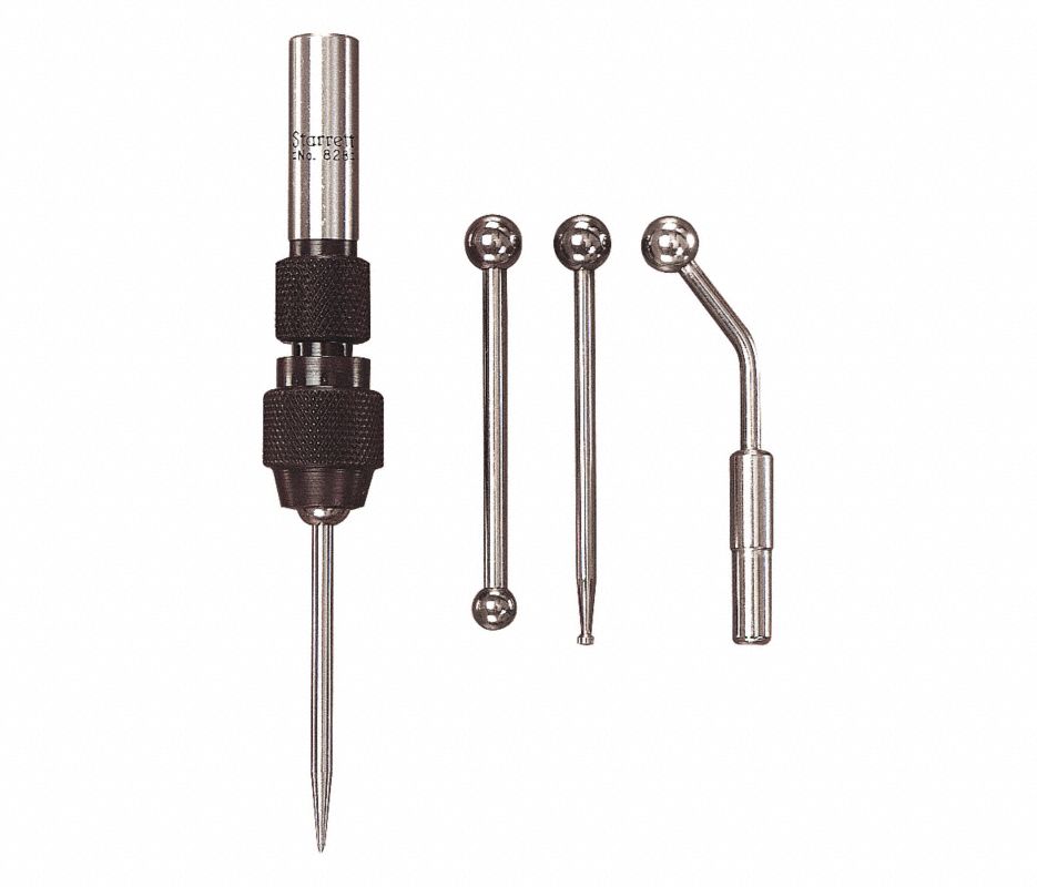
- Hold a dial indicator with a magnetic arm on the spindle head or in the spindle using the wiggler dial indicator mount.
- Starting at the side with the corner firmly tightened down walk the dial indicator to the fixed face of the vice until the dial reads zero.
- Slowly jog the dial along the axis parallel to the fixed face of the vice, once at the opposite end, tap the vice lightly with a mallet/dead blow hammer/etc until the dial indicator reads zero
- Jog back to initial side to check that it did not shift.
- If your reading reads the same touching along a single axis you know the vice is parallel to the table movement.
for a video demonstration please see link below
https://www.youtube.com/watch?time_continue=391&v=AZk5b1v7cu0
- Download the Templates for Fusion 360 from the mHub website

- In Fusion 360 preferences make sure Cloud Libraries are enabled

- Open Fusion 360's Data Panel
- In Fusion data panel scroll down to Libraries -> Assets -> CAM Templates
- Click Upload and select all the templates provided


6. To utilize, in your setup file in CAM right click and select "Create From Template"
